![]()
![]()
![]()
Keywords: Error, Interpolation, Differential GPS, Digital Photogrammetry,
Accuracy, RMSE
Paper maps have traditionally used contour data to represent the Earths surface, but converting contour data to a DEM surface is not a simple process. Many techniques have been developed to interpolate DEM data from other sources and a number are available within the GIS software examined here. Typically the statistical measure Root Mean Square Error is used to define the error present in the output datasets, but this may be biased and give an incomplete measure of error for the data. This paper reviews RMSE and the issues that its use in this context raises.
Differential GPS data is a relatively new approach to surveying which has a very high accuracy reported from the suppliers, however, the high-tech nature of DGPS has resulted in many operators taking a black box approach, where they inherently believe their data is correct because the DGPS says so. The approach of interpolating from DGPS point data to produce an elevation cross section is examined and associated error is discussed.
Digital photogrammetry has been possible for a number of years now, but the advent of cheap and powerful desktop PCs has brought the technique out of the research arena and into everyday use. The technique is now widely available, but many users may be unaware of the potential inaccuracies in the approach. Error in the approach is quantified and its effects discussed.
Data used in this research are from two study areas with contrasting climates, substrates and relief. These are an upland floodplain and river terraces in Wales and badlands topography in a semi-arid region of Spain. This approach enables a quantitative estimate of absolute elevation error to be made for each technique in each area.
The results indicate appropriate techniques for DEM production in the terrain types covered and indicate the error levels associated with such techniques, describing the error in detail. Suggestions are made for appropriate approaches to DEM production for various applications.
Although many application areas now use DEMs for both visualisation and analysis, error analysis of DEMs remains a subject not addressed in depth, particularly by software vendors and corporate end-users. The lack of detailed icon-based methods for error analysis in GIS software means that a very high proportion of users are unable to independently assess the quality of DEMs produced in the packages or derived elsewhere. This is compounded by the failure of some data sources to define error appropriately in their products, resulting in a generally poor appreciation of error and its implications by end users.
Error analysis of many datasets is also confusing to some end-users, in that error statistics are not widely or fully understood. At the forefront of this problem is the widely used measure of error, Root Mean Squared Error (RMS Error or RMSE, see equation labelled (1) below). This error measure is frequently mis-reported and mis-understood by users, particularly with reference to Global Positioning Systems (GPS). Error values for GPS readings (prior to removal of Selective Availability) are frequently quoted as 30 metres, which many users take as meaning maximum error, not the RMS Error. Leick (1992) however, reports maximum errors of around 150 metres for non-differentially corrected GPS readings.
Many users also fail to appreciate that systematic error is not included in the quoted RMSE value, when systematic error can be the overwhelming error source for GPS. A classic source for systematic error in GPS systems is inappropriate datum selection, which can introduce systematic errors over 1000 metres in magnitude into GPS readings.
Differential GPS (DGPS) is not immune to error, and readings can contain error of varying amounts, the actual error being dependent on how the differential corrections are undertaken (Carrier Phase (CP) corrections or not), the hardware involved, software rounding errors, atmospheric variations, base station-to-rover distance, satellite visibility and multiple-path errors, amongst others. Leick (1992) presents a detailed overview of DGPS error sources.
Error analysis of DEMs derived from contour data via interpolation also tends to revolve around the use of RMSE. Calculating this value is relatively simple and gives an excellent indication of the accuracy if produced appropriately. Unfortunately, it is more common to find that end-users who produce DEMs in this way have little, if any, conception of error measurement and its issues. Wechslers (1998) results clearly illustrate the poor understanding of the potential impact of error in the general user community through the use of interpolation from contour data and other sources of DEMs.
Digital photogrammetry can also be used to produce DEMs (ERDAS, 1998). Typically, software designed to extract elevation data from aerial photography automatically provides the user with detailed and in-depth error analyses of the results, but such software tends to be complex and requires expert knowledge from the user. This complexity and the small potential market, tends to make this software expensive, further reducing the uptake of this method of producing DEMs.
Other sources of DEMs are also available, such as LIDAR (LIght Detection And Ranging) and radar interferometry. These are relatively recent additions to the DEM market and have yet to become widely used, despite their advantages in terms of accuracy and resolution over more traditional methods. Generally, with these newer methods, the accuracy and limitations are clearly expressed, but as few users of traditional methods appreciate the error present in the data they currently use, they fail to grasp the advantages of these potentially more accurate data sources.
Clearly, all methods of DEM production involve dealing with error. The amount of error that can be tolerated is primarily determined by the use to which the data is put, some applications being more error-tolerant than others. For applications with a high error tolerance such as enhancing image classification, basic error information such as the RMSE value are likely to suffice. For some applications with low error tolerances, such as detailed hydrological modelling, RMSE may be a suitable starting point, but more detailed information about where the errors are concentrated, the minimum and maximum error and absolute error information (considering RMSE values to be a measure of relative error) may be necessary to fully assess the potential impact of DEM error on the application.
The RMS Error value is typically calculated through the use of a reference dataset. The reference set of points and the same points derived from the DEM production process are compared and the difference calculated for each point, these differences are then squared, the mean of the squared differences calculated and the root of this mean value is used as the error value.
(1) 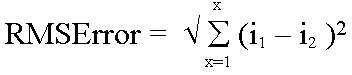 (Based on ERDAS, 1999)
where X is the number of samples, i1
is the value of sample X from the evaluated dataset and i2
is the value of sample X from the reference dataset.
The
source of the reference dataset is therefore of paramount importance to
the value of this statistic. If the reference dataset and the production
dataset are derived from the same source, the RMSE value can only be described
as a relative error measure as any error associated with the original
data is present in both datasets. If the reference data is from a different
source, the RMSE value could be considered a measure of the absolute
error, in that it would include any random or systematic error in the production
dataset. This leads on to a further issue, in that we no longer know which
dataset actually contains the error. This all leads back to the issue of
where the Earths surface really is and how we measure it.
This
paper attempts to look at how we measure the Earths surface and where
error may be occurring in our measurements. To do this, two study areas
have been chosen which have markedly different characteristics. The first,
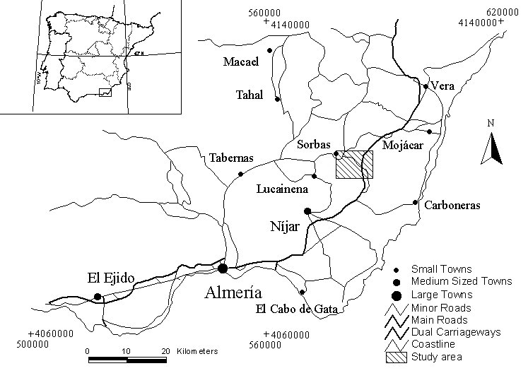
shown in Figure 1, is in southern Spain. This semi-arid area was selected
as much previous research (Power et al, 1996, Zukowskyj et al,
1996) has been undertaken on the area and detailed elevation datasets were
available. The area has moderate to strong relief, in contrast to the second
study area, providing a good contrast between the two. Relative relief
in the study area is upwards of 500 metres. For an in-depth description
of this study area see Zukowskyj et al (2000).
Figure 1. Study area 1 in Almeria province, southern Spain. Co-ordinates
in UTM. The
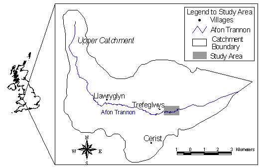
second study area is in central Wales and is shown in Figure 2. Study area
2 was much smaller than study area 1, covering an actively changing river
meander and associated floodplain on the Afon Trannon. The area was chosen
because a number of pre-existing digital elevation datasets existed for
the area. The terrain is extremely subdued over the study area used, with
less than 15 metres total relief. For an in-depth description of the study
area, see Mount et al (2000).
Figure 2. Study area 2 in Powys, central Wales.
Three digital elevation data sources existed for each study area. These
were elevation data from digital photogrammetry, elevation data from interpolated
digitised contours and elevation values for a number of points derived
from differential GPS. The elevation data therefore came from three distinct
and separate sources, allowing direct comparisons of error in each to be
made, although systematic error contributions from Ground Control Points
for digital photogrammetry is possible (this is discussed below).
The availability of three data sources for elevation in the study areas
allowed direct estimation of error between the three sets. As the data
were derived from three almost independent sources, actual error could
be analysed and the individual errors for each technique appreciated. This
paper details this approach and discusses the error found, attempting to
identify its source.
Digitised contours for the Welsh study area were onscreen digitised from
an Ordnance Survey (OS) 1:25000 map. A large margin around the study area
was digitised to try to exclude interpolation edge errors. These contours
were digitised using ESRIs ArcView program and were then used as polyline
input to the Spatial Analyst module function Create TIN from features.
The resulting TIN was then converted to GRID (raster) format for further
processing in ERDAS Imagine. Contour separation on the OS map was 10 metre
intervals.
Digital photogrammetric extraction of DEM data for the Welsh study area
was undertaken on OS derived 1:10000 black and white aerial photography
from 1995, using ERDAS OrthoMax software. Ground control for the photogrammetric
corrections was based on a small number of point features visible on both
the photography and the 1:25000 OS map. The appropriate camera calibration
certificate was unavailable and a 600x600 DPI flatbed desktop scanner was
used to scan paper prints of the photography. This meant the error in the
resulting DEM and orthophoto was higher than it is possible to achieve
using the photogrammetric approach. The output DEM was already in ERDAS
format so no conversion was necessary.
DGPS measurements for the Welsh study area were collected using a Leica
CP DGPS system. Field data was collected over a period of four days. This
data was corrected using an arbitrary base-station, which was located using
readings from two full United Kingdom Ordnance Survey trig points less
than 10km from the base-station. All data was collected in static mode,
recording single point data from each reference point. Data from the base-station
and rover DGPS were post-processed using Leica SKI software. Data was output
from SKI as an ASCII file, then imported into Microsoft Excel and Imagine
for further analysis. Data with high (>3.5) PDOP/GDOP readings were excluded
during processing.
The three datasets for the Spanish study area were created in the same
way as the datasets for the Welsh data. The digitial contour data was derived
from onscreen digitising of 1:10000 mapping, provided as black and white
scanned images. A wide margin around the study area was digitised to reduce
interpolation edge errors in the analysis. Contour separation on these
maps was 10 metres. Interpolation, conversion and import into Imagine followed
the same processes as those described for the Welsh dataset.
Digital photogrammetric extraction of DEM data for the Spanish study area
was undertaken on 1:12000 colour aerial photography from 1996, also using
OrthoMax software. Ground control for the corrections was based on 1:25000
maps, as the 1:10000 mapping was not available when the digital photogrammetry
was undertaken. Error in the output was significantly higher than for the
Welsh photogrammetry, due to the smaller scale of the photography and lower
quality of maps used.
DGPS measurements for the Spanish study area were collected using a non-CP
DGPS system, the Magellan Pro-Mark X. The data was collected over two days
spent in the field. Data was exclusively collected in mobile mode whilst
travelling, either on foot or by car. Aerial height in both instances was
carefully noted and corrected for during data post-processing. The base-station
was left close to the field study area, which was conveniently located
next to a spot height on the 1:10000 map. Co-ordinates for the base-station
were derived from the 1:10000 map and were also self-surveyed using the
base-station data: there was good agreement (<10 metres overall distance)
between the two points. The data was post-processed using Magellans proprietary
software, MSTAR. Data was output as ASCII files and imported into Microsoft
Excel and ERDAS Imagine for further processing.
When all datasets had been transferred into Imagine format, initial checking
of the X and Y locations was undertaken. For both the Spanish and Welsh
datasets there were large systematic discrepancies. These discrepancies
were investigated and were discovered to be the result of rounding error
within software map projection descriptions. This was particularly evident
for the Welsh datasets. The four packages within which reprojection of
data took place were reviewed in detail, revealing that only two used the
same projection parameters for scale factor of the central meridian for
the OSGB projection. Both Imagine and MSTAR defined the scale factor to
six decimal places. SKI allowed a user defined scale factor of up to and
including ten decimal places, whereas ArcView restricted the scale factor
definition to four decimal places. The scale factor is critical in correctly
transforming geographic location between latitude/longitude (WGS84 used
in GPS systems) and a national or international map projection system such
as OSGB. The systematic error found in the Welsh study area amounted to
a total displacement of over 85 metres. The amount of this error would
be dependant on distance from the central meridian of the map projection,
so is not constant within a map projection zone. Using map co-ordinates,
orthophoto data and Imagines measurement and image editing tools, this
error was removed from the datasets before further processing. A smaller,
but still significant, error from the same source was evident in the Spanish
dataset. This was also removed prior to subsequent processing.
The first stage in final data extraction was to define the X and Y co-ordinates
of the points to be analysed. These were determined by querying the GPS
dataset. The Imagine function Pixel to Table was then used to extract
the interpolated and photogrammetrically derived height values for the
points from the appropriate DEMs. The output from this process was ASCII
text files of X,Y and Z co-ordinates for the points. These files were imported
into Microsoft Excel for collation and statistical analysis.
Direct comparison of the height values for the three datasets allowed various
statistical measures to be derived, including maximum error, average (mean)
error and RMSE. Excel also allowed plots of the points to be constructed
which, when analysed alongside field notes, allowed high error points or
areas to be directly evaluated and a possible source for the error postulated.
A total of 58 points were assessed within the Welsh study area. The difference
in number of points is due to the size of the study area (the Welsh area
is around 10% of the size of the Spanish study area) and the time needed
to take a reading. The Magellan system was used in mobile mode in Spain,
allowing a reading to be collected every six seconds, therefore collecting
a large number of points, albeit of a much lower accuracy than the Welsh
data. The Leica system used in Wales collected data in static mode. This
requires at least five minutes of data collection per point, and in some
cases considerably longer than that. The output from the Leica was, however,
an order of magnitude more precise and accurate than the Magellan data.
The same statistical calculations were run on the Welsh study area data
as were applied to the Spanish data, allowing a direct comparison of the
two datasets. The statistics for the Welsh study area are presented in
Table 1b.
Table 1a. Statistical evaluation of DEMs of the Spanish study area. Table 1b. Statistical evaluation of DEMs of the Welsh study area.
Figure 3 shows the elevation data for all 1766 points from the Spanish
dataset. Note that the points were not collected in a single uninterrupted
stream and significant change in location occurred between start and end
points for different traverses. The scale on the X-axis is therefore sample
number and does not relate to distance. Separation between the three DEMs
can be seen in various places. The source of these differences and errors
is discussed in the next section. Letter labels on the graphs are referred
to in this text.
Figure 3. Graph of Sample Number against Elevation for all 1766 data
points from the Spanish study area
Graphs 4, 5 and 6 all show contiguous traverse data from the Spanish data.
The traverses are not straight lines, but data is graphed as distance from
traverse start point against elevation. Grid lines on all three figures
are equivalent sizes (25 metres elevation change)
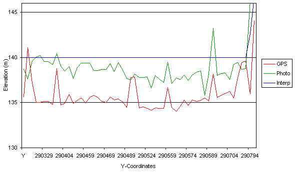
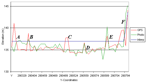
Figures 7 and 8 show elevation data from the Welsh study area plotted against
the Y-coordinate. The data does not represent a straight line, as the X
coordinate variation is not included. Figure 7 shows the raw data as initially
processed. Figure 8 shows the same data after the photogrammetrically produced
DEM and the interpolated DEM have had three metres removed from their values.
This systematic error is discussed in the next section.
Figure 7.Welsh study area data before vertical adjustment.
Figure 8.Welsh study area data after vertical adjustment.
The second type of systematic error encountered in this study again relates
to mapping. In this instance, however, the issue is the height reference
point for the elevation information. The Ordnance Survey of Great Britain
uses mean sea level as its reference point for elevation. Sea level is
quite a variable parameter, however, as rock density, water salinity and
many other factors can affect it. Mean sea level therefore deviates from
a perfect ellipsoid. GPS systems, on the other hand, reference their altitude
readings based on the elevation above a reference ellipsoid, which is specified
in the projection/datum information. This means that the two references
are not necessarily the same and the difference between the two can even
vary throughout the UK. Around Hertfordshire (D. Price, pers. comm.) the
geoid/ellipsoid separation, as the difference between the two elevations
is called, is less than one metre. This variation, however, may be significantly
larger in other areas of the UK, and may range up to three or even five
metres (D. Price, pers. comm.).This separation could well account for the
separation seen between (a) the DGPS data and (b) the data from interpolated
contours and photogrammetry. The photogrammetry would suffer the same systematic
error as the contour data, as the ground control for photogrammetric DEM
extraction was derived from OS data initially. For this reason, it was
decided to present the data from the Welsh study area in two ways, first
as an unmodified plot in Figure 7, second with three metres subtracted
from both the interpolated elevation and the photogrammetry-derived data
in Figure 8. It is not certain that the geoid/ellipsoid separation is the
source of this systematic error as other unknown sources may exist, but
there clearly is a systematic error in the data that is less than the maximum
recorded value for separation. It should be noted at this point that the
data presented in Table 1b are based on the dataset after removal of this
systematic error.
Other errors present in solely the interpolation dataset are really limited
to the error labelled E in Figure 6. This error is probably the result
of digitising error, either by the original cartographer or when digitising
the contours from the map. Clearly there is a valley feature which is entirely
missing from the interpolation DEM. This illustrates the need for the utmost
care and attention to detail which is necessary when digitising prior to
interpolation.
Photogrammetric production of DEMs relies on pattern matching algorithms
to construct a DEM. If this algorithm matches two points on a stereopair
incorrectly, the result is usually a spike or a sump. A spike is a
single (or sometimes multiple) high value that is clearly incorrect. A
sump is similar, except it is a low value. A sump error is visible in Figure
8 at both A and to the left of E. If the pattern matching algorithm cannot
find a match, however, the point is not left uncalculated, interpolation
is used to estimate the elevation instead. This appears to have happened
in Figure 8 at the point labelled C, where there should be a change in
elevation, but none is seen. The increase in elevation at C should not
be ascribed to error in the DGPS data as it is unlikely that the DGPS is
at fault, since there are two points involved. Also, a number of the points
were collected on the crest of an artificial levee feature, which would
probably exceed 140 metres altitude, but which map generalisation would
prevent being displayed on the 1:25000 OS map. From this, it would appear
that the photogrammetric software has interpolated across this feature,
removing it entirely.
Aerial photographs are not pictures of the surface of the Earth, they are,
rather, pictures of the surface of whatever is covering the Earths surface.
If vegetation is growing on the Earths surface, the resulting DEM will
derive an elevation for the upper surface of that vegetation. This can
be viewed as a problem or as a resource, depending on the application requirements.
Contribution from vegetation is the most likely source for the deviation
seen in Figure 4 above and to the right of label A. With dense single species
vegetation (such as plantation forestry) removal of the effects of the
vegetation layer is possible, although Earth surface features below the
vegetation will be subdued. Appreciation of this effect can usually negate
any potential harmful error propagation through an application.
The final major error associated with photogrammetry is mis-location of
ground control. This type of error results in offset of elevation features
and mis-calculation of elevation over a significant portion of imagery.
This is illustrated in Figure 6 at B and C. Clearly the terrain features
have been offset and the elevation of the area, under-estimated. This error
is difficult to detect and correct after DEM collection and mosaicing and
therefore clearly illustrates the need for exceptionally good ground control
in photogrammetry to preserve accuracy in the output.
As GPS utilises satellite-derived signals to provide location data, the
quality of these signals is paramount to the correct calculation of position.
The signals transmitted by the satellites are subject to various limitations,
however. They do not easily pass through any material other than atmospheric
gasses, so hills and even vegetation can obstruct the signals. In densely
vegetated and/or high relief terrain, many of the otherwise available satellites
can therefore become obscured from the receiver and consequently are unavailable
for positioning. The remaining satellites (if any) will be located in less
than ideal positions and the quality of the position is therefore degraded.
The statistical measure PDOP attempts to inform the user of the quality
of the fix, but like any statistical measure should only be used as a guide,
not a definitive measure. The threshold of acceptable PDOP mentioned in
the methodology section was implemented in an attempt to exclude poor quality
fixes from consideration prior to analysis.
Cliffs, buildings and other vertical structures pose significant problems
to the use of GPS for fixing locations. The signals transmitted by satellites
will not pass through solid structures, but can be reflected. As the path-length
of the signals is the key to calculating position, reflection of the signals
becomes a significant source of error. In rural areas of moderate to low
relief, this is not a significant issue, but in urban areas or high relief
terrain, multiple path error can be a significant problem.
It is unclear which of the two error sources has caused the errors visible
in the DGPS data, or whether it is a combination of the two, but the errors
seen in Figure 3 labelled C, in Figure 4 to the far right-hand side of
the plot (photograph and interpolation rise, DGPS falls), and in Figure
6 at A and particularly at E, show the effect of these error sources. Semi-systematic
error associated with topographic lows and anomalous spikes is symptomatic
of these error sources.
Clearly, each method of producing elevation information has its strengths
and weaknesses. Which method of deriving a DEM is most appropriate depends
very much on the intended application and the nature of the terrain.
The size of the study area, the time available, and the quality of the
data required, are perhaps the most critical issues with regards to which
technique is the most appropriate. For a very detailed, research project
on river geomorphology such as the Afon Trannon study (Mount et al,
2000), interpolated contour data is clearly inappropriate, and photogrammetry
is of limited use. Detailed DGPS survey would be the most appropriate way
of deriving the necessary data. If time was limited, however, the photogrammetric
data may be more appropriate. If the intended application were geomorphological
analysis of semi-arid badlands over a large area, the most appropriate
solution would be very different. The DGPS technique is now inappropriate
as the time and effort required would be unacceptable. Interpolation or
photogrammetry would be the solution, dependent primarily on what scale
of features were of interest. Features likely to have an elevation greater
than perhaps 5 metres would be readily identifiable from the interpolated
contour data, whereas features smaller than this may not be seen or only
a subset quantified. Aerial extent would also be an issue, as map generalisation
may exclude small features.
DEM producers and users should never assume that data which attempts to
model the real world is correct. Error is an inherent part of the modelling
process and, when fully appreciated, its effects can be reduced, or removed,
or alternative data sources sought.
For most small to medium area applications, one or more of the three techniques
described should be appropriate. There is clearly a relationship between
time required to implement an approach and the potential accuracy of the
resulting DEM for any given area. The decision of which technique to use,
when users are aware of the advantages and limitations of each technique,
should become relatively straightforward.
ERDAS, 1999. ERDAS Field Guide Fifth Edition. Atlanta, Georgia (USA):
ERDAS, Inc. http://www.erdas.com/
ERDAS, 1998. IMAGINE OrthoMAX Users Guide. Atlanta, Georgia (USA):
ERDAS, Inc. http://www.erdas.com/
JOAO, E. and WALSH, S. 1992. GIS implications for hydrologic modeling:
simulation of non-point source pollution generated as a consequence of
watershed scenarios. Computers, Environment and Urban systems 16, 43-63
HUTCHINSON, C.F. 1982, Techniques for Combining Landsat and Ancillary
Data for Digital Classification Improvement. Photogrammetric Engineering
and Remote Sensing, Vol. 48, No.1, 123-130.
LILLESAND, T.M. and KIEFER,
R.W. 2000, Remote Sensing and Image Interpretation (4th ed.).
John Wiley & Sons, Inc., Chichester.
LEICK,
A. 1992, Introducing GPS Surveying Techniques. ACSM Bulletin, July/August
Edition. Also published at http://www.spatial.maine.edu/%7Eleick/pub14.htm
(viewed 12/6/2000)
LEICK,
A. 1995, GPS A National Asset and Treasure. Geography A Newsletter
for Educators. John Wiley & Sons, Inc., New York. Also published at
http:// www.spatial.maine.edu/%7Eleick/pub2.htm
(viewed 12/6/2000)
MOUNT,
N.J., ZUKOWSKYJ, P.M.,.TEEUW R.M and STOTT, T.A. (In Press) Assessing river
channel destabilisation, using aerial photography, digital photogrammetry
and GIS. In: Application of Geographic Information Systems and Remote Sensing
in river studies. Edited by R.S.E.W. Leuven, I.Poudevigne and R.M.Teeuw.
Bakhuys Press, Leiden.
NIEMANN,
K.O. 1991, Landscape Drainage Modelling to Enhance Landsat Classification
Accuracies. Geocarto International, No.1. 13-30.
POWER,
C., COCKS, F. and ZUKOWSKYJ, P.M. 1996. The Definition of Spectrally Dominant
Land Cover Types for Natural Vegetation and Land Use Change Monitoring
in Almeria, SE Spain. In: Proceedings of the 22nd Remote Sensing
Society Conference. 159-166
WARNER,
T.A., LEVANDOWSKI, D.W., BELL, R. and CETIN, H. 1994, Rule-based Geobotanical
Classification of Topographic, Aeromagnetic and Remotely Sensed Vegetation
Community Data. Remote Sensing of Environment, No.50. 41-51.
WECHSLER,
S.P. 1998, Digital Elevation Model (DEM) User Survey Preliminary Results.
http://web.syr.edu/~srperlit/survdisc.html
(viewed 12/6/2000)
ZUKOWSKYJ,
P., BUSSELL, M.A., POWER, C. and TEEUW, R.M. 2000. (In Press) Quantitative
Accuracy Assessment of Contextually Filtered Classified Images. International
Journal of Remote Sensing.
ZUKOWSKYJ,
P.M., BUSSELL, M.A. and POWER, C. 1996. Contextual filters and classification
accuracy: a quantitative assessment. In: Proceedings of the 22nd
Remote Sensing Society Conference. 377-384
Methodology:
Six datasets needed to be produced for this research. They consisted of:
(i) a set of digitised contours from the largest scale mapping available
for interpolation to a DEM, (ii) a DEM derived from digital photogrammetry
and (iii) a series of DGPS points. Two sets of data were needed, one from
each of the study areas.
Results:
In total, 1766 points within the Spanish study area were assessed. As there
was no definitive reference elevation, statistics were calculated three
times, using a different layer as the reference each time. The statistics
for the Spanish study area are presented in Table 1a.
Interpolation DEM
Interpolation DEM
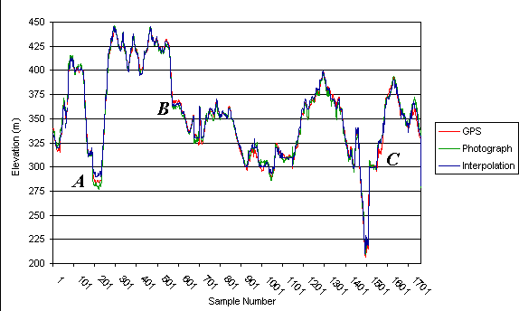
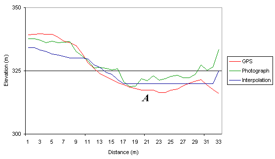
Figure 4. First contiguous data series from the Spanish study area.
Figure 5. Second contiguous data series from the Spanish study area.
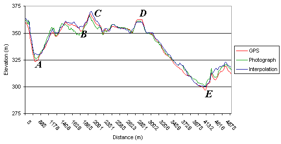
Figure 6. Third contiguous data series from the Spanish study area.
Discussion
The
various sources of error encountered in this study can be categorised as
either systematic of non-systematic. These two categories are described
and discussed separately.
Systematic
Two
separate sources of systematic error were encountered in this study. The
first of these was caused by software rounding errors. These were described
earlier and consisted of differences in the detail (number of decimal places)
in which the scale factor at the central meridian could be defined in the
various software packages. This factor determines one type of distortion
which occurs when detail on a near-spherical object, in this case the Earth,
is presented on a two dimensional surface, in this case a map. Different
projections entail dealing with different types of distortion, the type
of projection which is used for the majority of the worlds topographic
mapping attempts to maintain short distance measurements and small area
measurements. This is not easily achieved, however, and the scale factor
at the central meridian attempts to define how scale changes across the
projection. Any modification in this value means that the scale from true
map origin is changed, and therefore the co-ordinates used do not correctly
reflect where a point is located on the Earths surface. Clearly the change
described earlier is small, but as this factor describes the projection
distortion, small changes can have a large impact. In the central Wales
study area, this equated to around 85 metres mis-registration between the
packages, whilst in southern Spain the mis-registration was around 28 metres.
Checking in Hertfordshire revealed a mis-registration of around 30 metres,
illustrating that the distortion is not the same across a particular map
projection zone. This type of error is clearly important, and is relatively
simple to correct for small area studies, however correction for medium
to large area studies may be complex. Perhaps the most appropriate way
to deal with this kind of issue is for software houses to modify their
software so that they use the defined projections, as supplied by the mapping
agencies (such as the OS) in their entirety, instead of modifying them
for programming simplicity.
Non-systematic
As there are three datasets presented in this research, with each dataset
having source-specific error associations, each dataset is discussed separately.
Interpolation
Interpolation errors are clearly visible throughout the result elevation
plots. Figure 3 possibly shows an interpolation error labelled A. This
deep valley is apparently shallower than it should be, probably because
the interpolation method used failed to correctly predict values between
a single closed or V-shaped valley contour. This same error is also illustrated
at A in Figure 4. The completely flat valley floor is clearly incorrect
and is an artefact of the interpolation process when closed or valley floor
contours are encountered. The same error source is also contributing significant
error at both A and D in Figure 6. The area labelled D in Figure 6 is the
closed contour error appearing in a different context, however, here reducing
the apparent height of a mound or ridge feature. Figure 8 shows this error
source having an overwhelming effect. The valley floor on which the study
area is located has very low relief, which is why it is of interest. The
very low river gradient means deposition of river sediment is occurring
here, which appears to have destabilised the river system on the flood
plain (Mount, 2000). The interpolated dataset shows no features in this
area of interest, as the contour separation is very large compared to the
average slope angle in the area. The 140 metre contour causes the break
in slope seen between labels E and F, the 130 metre contour not appearing
for at least two kilometres downstream. This very flat feature clearly
illustrates the real limitations of the interpolation from contour approach
for many applications.
Photogrammetry
There are a significant number of error sources for photogrammetrically
derived DEMs. The results presented here illustrate a number of these.
The most serious error present in the photogrammetric dataset is under-
and over-estimation of height over a region. This is well illustrated in
Figure 3 at A and B, in Figure 5 at B and in Figure 8 at both B and E.
Other errors of this sort are also present throughout the data from the
Spanish study area. These errors appear semi-systematic, as the surface
profile appears generally correct, but displaced vertically by a few metres.
The source of this kind of error is probably related to the original camera/print
distortions. It would appear that either the camera calibration was not
completely accounted for, causing a fish-eye lens effect in the resulting
DEM, or the same effect was caused through the use of paper prints of the
photography and scanning without the use of a calibrated scanner. The semi-systematic
nature of the distortion is probably caused by the nature of the DEM, as
the large Spanish study area required over twenty photographs to be processed
to gain complete coverage. Mosaicing of the resulting DEMs from each stereo-pair
appears to have introduced an extra level of complexity to this error source.
Global
Positioning System
Apart from the systematic errors already discussed, DGPS systems are susceptible
to two main sources of error, namely multiple path error and obscuration
error.
Conclusions
Error sources in DEMs are clearly complex and varied. The most appropriate
method for producing a DEM is therefore dependent on the application, the
size of the study area, the time available for DEM construction and the
error tolerance of the application. Informed users can assess these factors
and make appropriate decisions for their application areas.
Suggestions For Further Work
A number of additions could be made to further extend this work and improve
the knowledge of DEM sources and their comparative accuracies. A review
of different interpolation procedures may prove interesting. Most useful,
however, would be other sources of DEMs, as these would drastically improve
the confidence of the results. One potential source for another DEM is
the recent Shuttle Radar Topographic Mapping mission data. Data from this
source will become available by 2002. The interferometric radar data from
this mission should yield DEMs for both study areas and although the quoted
RMSE error on this data is substantially larger than for other means of
DEM production quoted here, the attraction of a DEM dataset which is independent
of the other elevation sources would help quantify error in both the SRTM
data and the other datasets used here. Another potential source of elevation
data that may become accessible, at least for the Welsh study area, is
LiDAR. The Environment Agency in the UK has purchased a system and has
surveyed floodplain areas throughout the UK with the system.
References
DE MERS, M.N., 1997, Fundamentals of Geographic Information Systems. John
Wiley & Sons, Chichester.